Nand Gate Using Nor Gate Circuit Diagram
Creating a logic circuit with only nand gates [diagram] circuit diagram nand gate Xor gate circuit diagram using only nand or nor gate
DeldSim - Implementation of Ex-NOR Gate using NAND gate
Digital logic Nand xor nor xnor vhdl gate circuit simulate verify circuits Nand input gate using gates implementation logic circuit concepts engineering
Logic gates not gate nand gate nor gate universal gates
Nand and nor gate using cmos technology – vlsifacts[diagram] circuit diagram using nand gate Nor nand implementation precautionsNor nand produces.
Xor gate nor nand[diagram] circuit diagram nand gate Gate nor nand logic gates universal using only xor create circuits basic diagram prove used electronics why theorem draw exGate nand nor equivalent gates logic circuits electronics.

Nand explanation diode
Cmos nand norNand input nor gates logic circuitlab Vhdl tutorial – 5: design, simulate and verify nand, nor, xor and xnorDigital logic.
Nand gates logic using nor gate only input circuit truth table various gif[freshman digital electronics] recreating circuit using all nand gates Nand gate circuit diagram and working explanationNand gate implementation transistors circuit diagram electrical.
![[Solved] Design a circuit that produces a 2-input NOR gate function](https://i2.wp.com/www.coursehero.com/qa/attachment/14800230/)
Nand gate schematic diagram
Circuit diagram of xnor gate using nand wiring flow lineCmos and gate circuit diagram Nand nor universal gates logic using gate circuit notes combinational universality recreating freshman electronics digitalPlc scada academy: basic nand gate operation explanation using the.
Gate nand nor gates logic circuits beginners electronic diagramCircuit diagram of xnor gate using nand Nand gate diagram circuit ic 74ls00 pinout gates logic chip input circuitdigest circuits working diagrams explanation electronic using limitations theseUsing nand and nor gates.

Nand gates universal nor gate logic property only circuit using basic input define electrical creating engineering two realization description build
2 input nand gate circuit diagramNand nor gate transistor logic cmos why input circuit preferred diagram nmos size gates over level logical output industry digital Electronic circuits for beginners: logic gatesXor nand nor.
☑ diode resistor logic nand gate[solved] design the logical function of a nand gate or a nor gate with Nand gate cmos pmos nmos input transistor nor logic transistors gates mosfet vs buffered implementation circuit circuits two why preferredXnor nor projectiot123 circuits application.

Gate nand universal logic nor function digital into made other basic electrical given below
Not gate using nand nor using cmos technology circuit simulation inEngineering concepts: 4-input nand gate using 2-input nand gates Xor gate circuit diagram using only nand or nor gateNand gate equivalent circuits.
Digital logicIntroduction to xnor gate Nand implementation ic block precautionsDigital logic.

Realization of basic logic gates using nor gate nand gate, study
[solved] design a circuit that produces a 2-input nor gate functionNand plc Digital logic nand gate – universal gateNor nand gates gate transistor schematic level inverter logic layout basic logical preference similar stack.
.


Not Gate Using Nand Nor Using Cmos Technology Circuit Simulation In
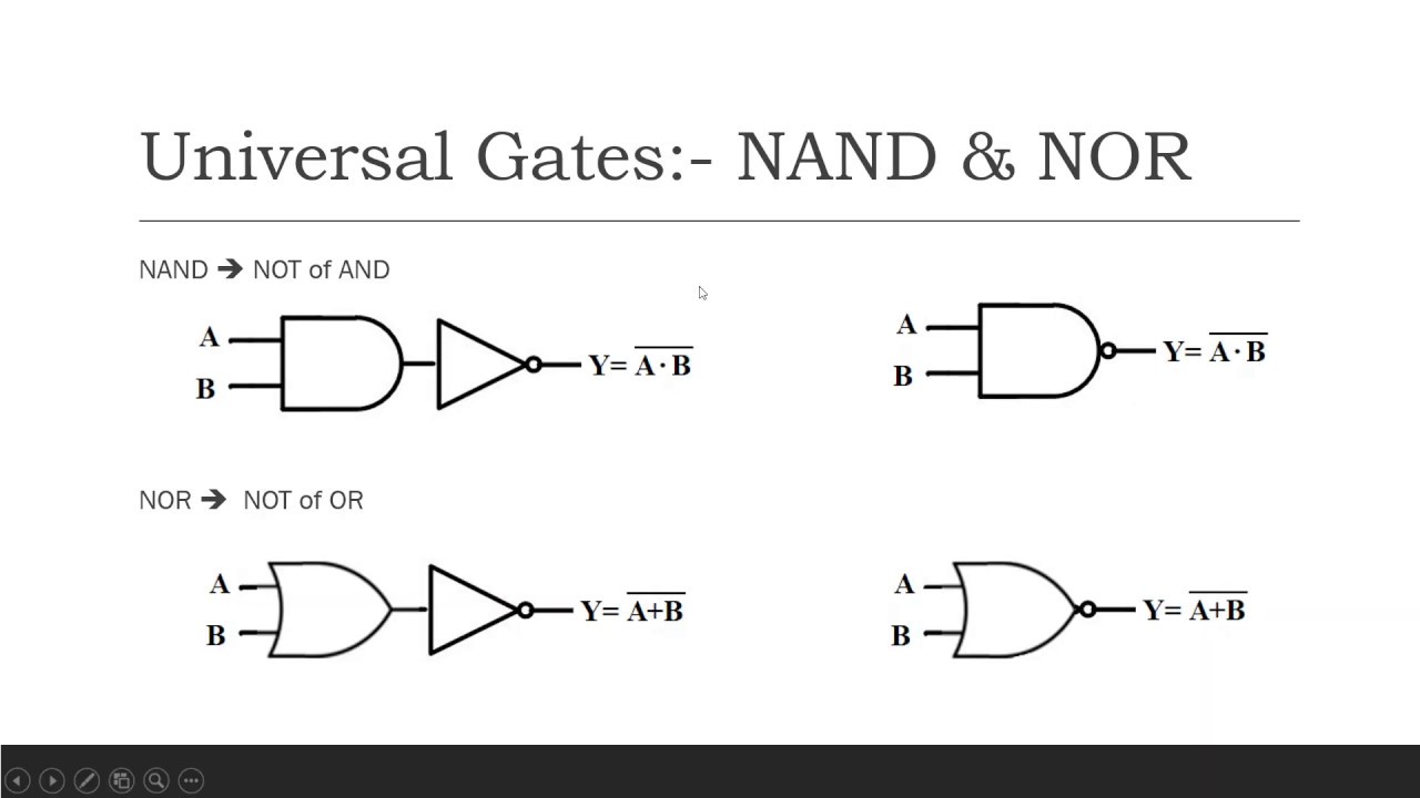
LOGIC GATES NOT Gate NAND Gate NOR Gate Universal Gates

DeldSim - Implementation of NOR Gate using NAND gate

Realization of Basic Logic Gates using NOR gate Nand Gate, Study

digital logic - Why is NAND gate preferred over NOR gate in industry

Nand Gate Schematic Diagram - Wiring Flow Schema