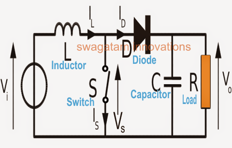
Boost Converter Block Diagram
Closed loop control system of buck-boost converter with discrete pid Boost converter circuit topology. Converter boost adapted regulated
microcontroller - Boost converter help - Electrical Engineering Stack
Converter inductor converters basics Boost block diagram converter system figure dataweek power electronics Converter circuit unidirectional
Converter schematic switching regulator
How boost converters workShows the schematic diagram of an isolated boost converter under study Block diagram of the proposed boost converterBlock diagram of the proposed boost converter controller..
What is boost converter? basics, working, operation & design of dcPfc circuit active diagram converter ccm boost block correction factor power ppt powerpoint presentation Converter toshiba lineupBuck boost converter circuit theory working and applications.

(pdf) modeling and validation of a fuel cell hybrid vehicle
Boost converter block diagramBoost converter circuit using 555 timer ic Dc/ac boost inverter block diagramBoost converter.
Boost converter control block diagramDiode switches Ideal unidirectional dc-dc boost converter circuitBlock diagram of boost converter.

Modeling validation hybrid fuel cell vehicle
Current block diagram of the boost converter.Boost converter schematic How to choose components for boost converterBlock diagram of control-to-output for boost converter with peak.
Boost converter diagram dc simple circuit topology conduction converters voltage mode output discontinuous analysis schematic engineering equilibrium low four helpBoost converter block diagram 1: block diagram of boost converter with pwm feedback controlConverter inverter.

Ccm response control
A boost converter using (a) ideal switches, (b) a diode as theBoost converter components choose schematic circuitlab created using Boost converter circuit converters work homemade voltage relay capacitor process resultsConverter buck circuit boost dc diagram ac converters equivalent theory applications switching analysis four working evaluation equilibrium allaboutcircuits articles modelling.
Loop compensation of voltage-mode boost convertersConverter circuit Block diagram of the proposed boost converterBoost converter circuit.

1: a block diagram of a boost converter
Circuit block level diagram of the boost converter with pbc augmentedConverter boost pwm Circuit schematic of boost converterBoost proposed.
Block diagram of the proposed boost converterConverter topological Is there a universal tool for dc/dc voltage conversion?Boost converter circuit..

Waveform audit: my boost converter has an off-ramp!
Boost converter block diagram .
.


how to choose components for boost converter - Electrical Engineering

Boost Converter Block Diagram | Download Scientific Diagram

microcontroller - Boost converter help - Electrical Engineering Stack

Block diagram of the proposed boost converter | Download Scientific Diagram

Boost Converter Schematic - Bald Engineer

How Boost Converters Work | Homemade Circuit Projects